KTM’s 690 motor is a potent, compact powerplant that can be very reliable, if maintained correctly. In this ChanceMoto guide, we’ll walk you through one of the most common maintenance items: how to check and adjust valve clearances. We’ll also cover rocker arm inspection and replacement – another common maintenance item on this motor. Note that we are using a 2010 KTM 690 SMC for illustration purposes but the procedure is nearly identical for all 690 motors.
Required Tools & Parts:
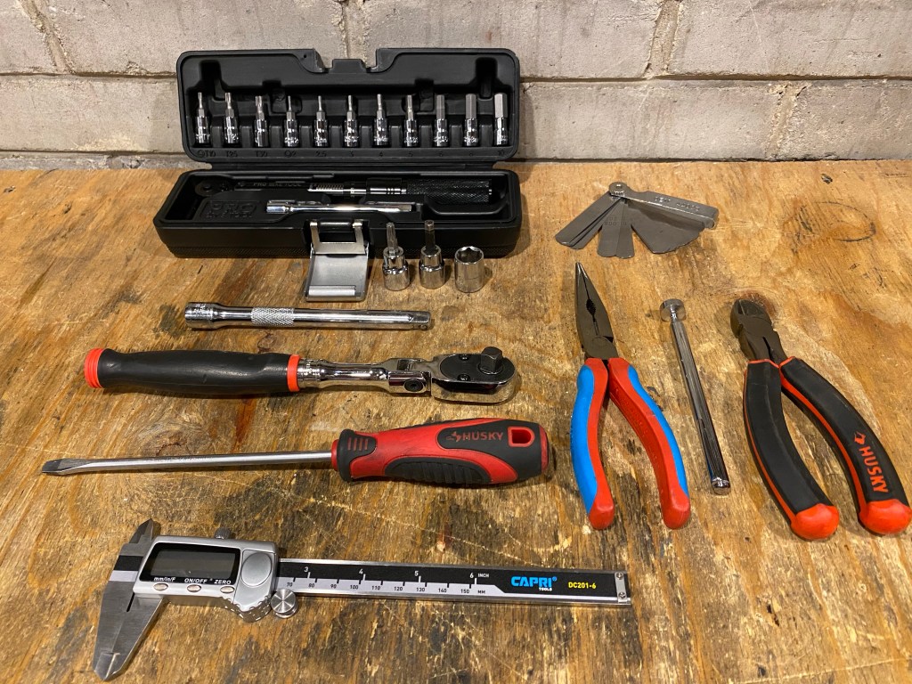
Ratchet, extension, socket set, hex set, torx set, torque wrench, pliers, long flathead screwdriver, feeler gauges, measuring calipers, magnet tool, 10W50 oil or assembly fluid, 10mm OD valve shims, zip ties, valve cover gasket (optional).
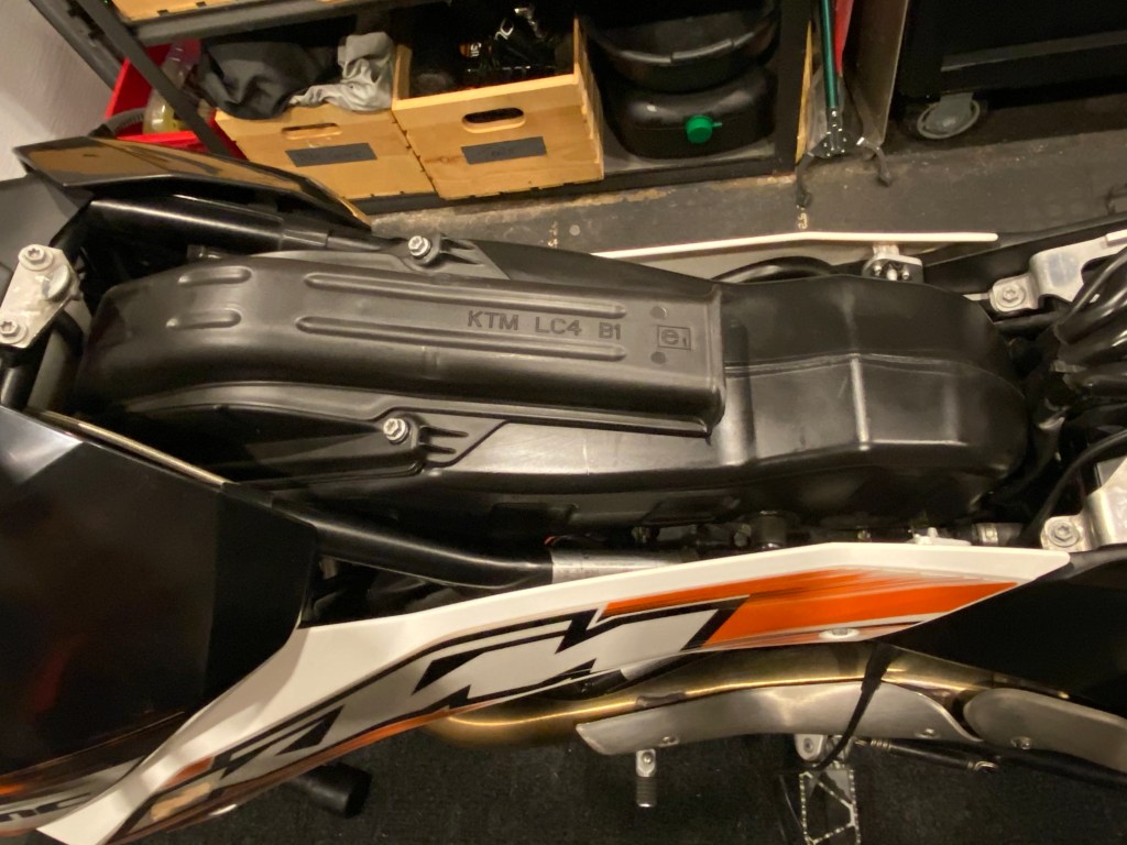
- Airbox Removal
The first order of business is to gain clear access to the top of the motor which requires the removal of the airbox. Begin by removing the left and right side front fairings.
There are 4 torx bolts and one clamp that hold the airbox in place (and secure it to the throttle body), in addition to a few hoses and sensor wires. Remove the 2 rear bolts first.
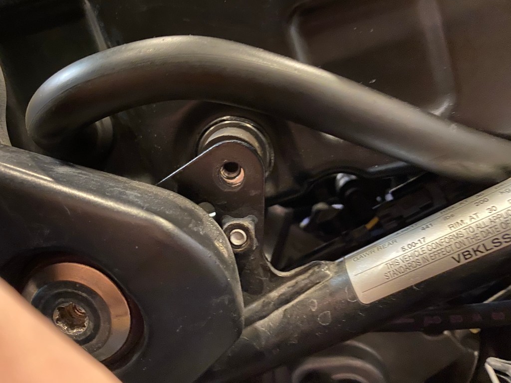
To gain access to the front right bolt, you will need to remove the voltage regulator. The bolt can then be accessed through a hole in the panel behind it.
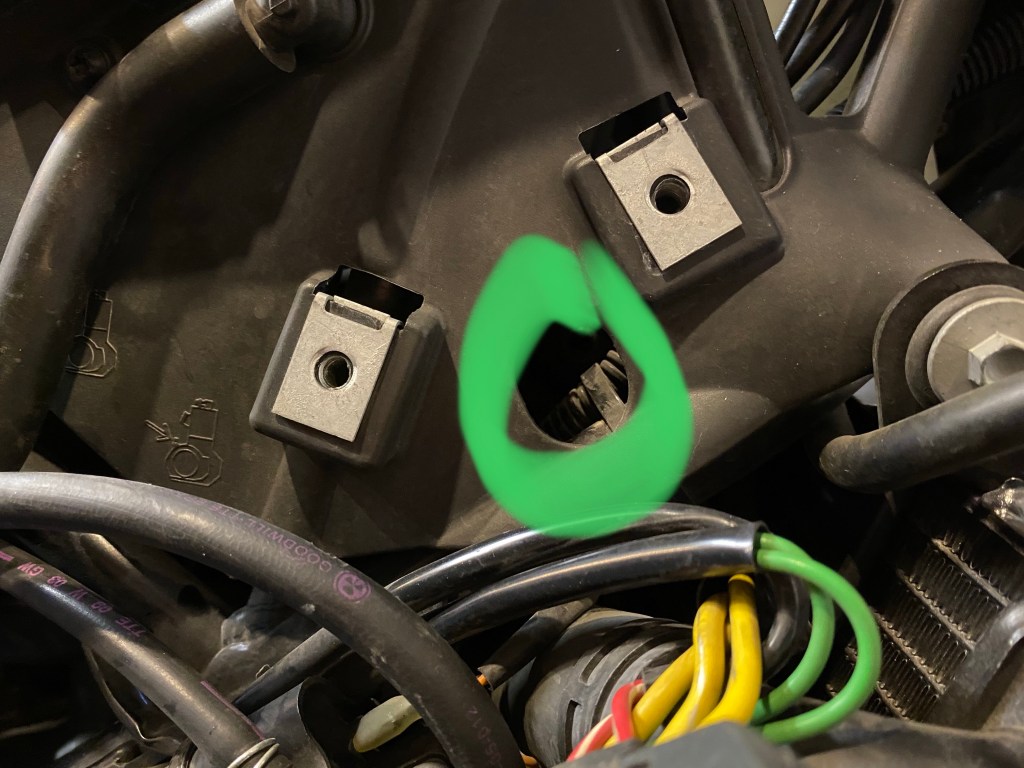
With the 4 bolts removed, you will need to disconnect the breather hoses and O2 sensor wire, located on the left side of the airbox. The hoses are held on with clamps which are easily removed with pliers. The O2 sensor cable is a “press & pull” style clip.
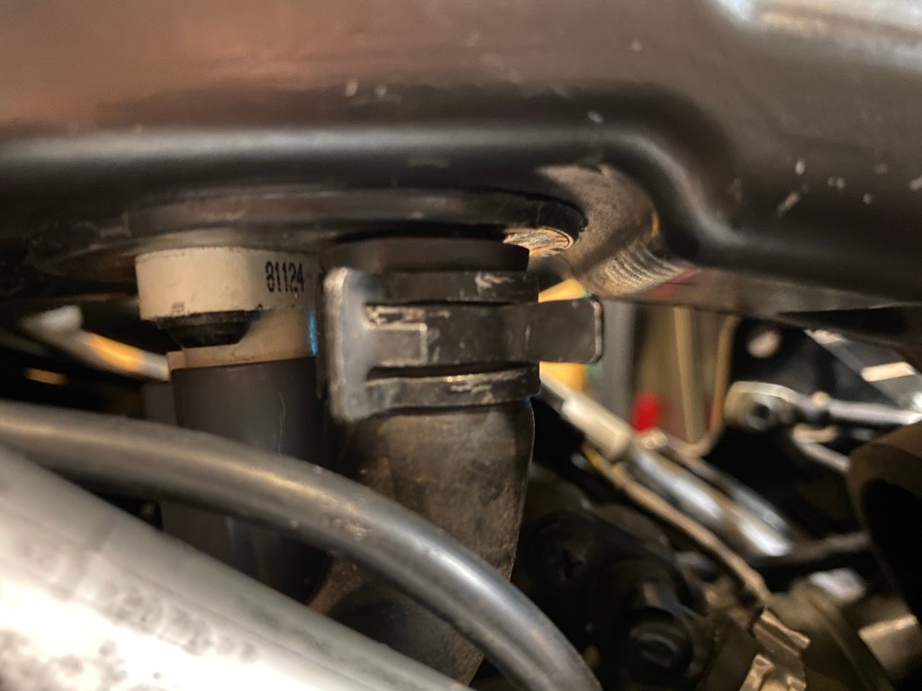
The last step to remove the airbox is to loosen the clamp that secures the airbox to the throttle body. Use a long flathead screwdriver to loosen the clamp until is moves freely. To remove the airbox, pull back first, then up, in order to dislodge the seal from the throttle body.

2. Valve Cover Removal
With a clear view of the valve cover, begin by stuffing a clean rag into the throttle body opening to prevent debris from getting in.
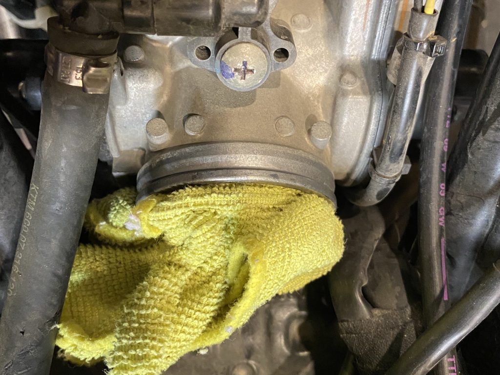
Next, clean any dirt from the area with a damp cloth. The idea here is to avoid getting any dirt into the motor throughout the rest of the valve service.
You can now disconnect the 2 breather hoses from the valve cover. You may need to cut a few zip ties and pull the hoses out of the way through the frame as getting the valve cover off and out is a tight fit.
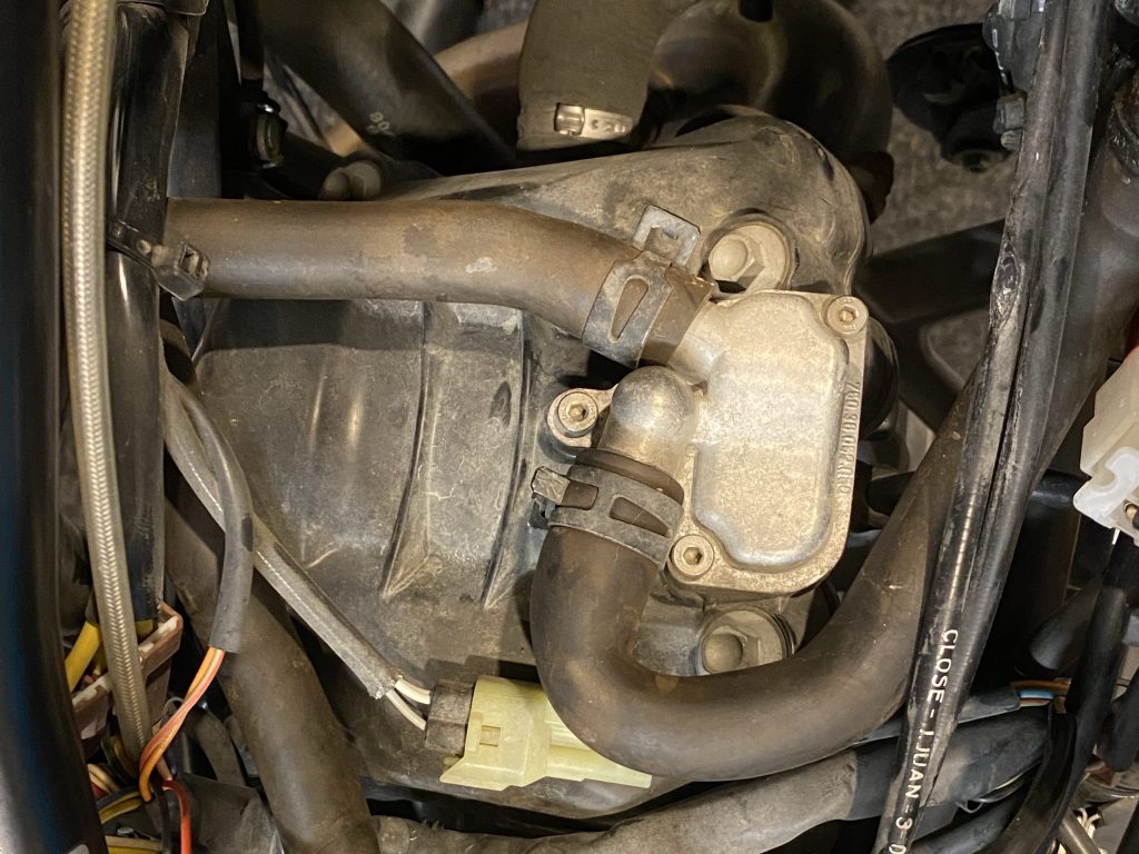
Remove the 4 bolts securing the valve cover and lift it out of the frame. You will need to rotate the valve cover and experiement with different angles to get it out. Note that the rubber gasket should also come off with the valve cover. Be careful not to damage it unless you plan on replacing it (always a good idea).
3. Rotate Motor to Top Dead Centre (TDC)
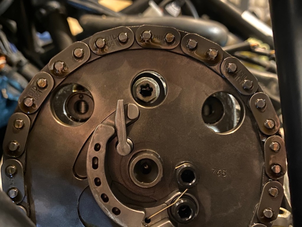
In order to take a proper measure of the valve clearances, the motor needs to be set to TDC. This is easy to do if you know what you are looking for. Begin by taking a look at the cam timing sprocket and locate the part of the sprocket with 3 holes as shown below. Note that the left and right outer holes should also be aligned as they will be used later on to extract the rocker arm rods.
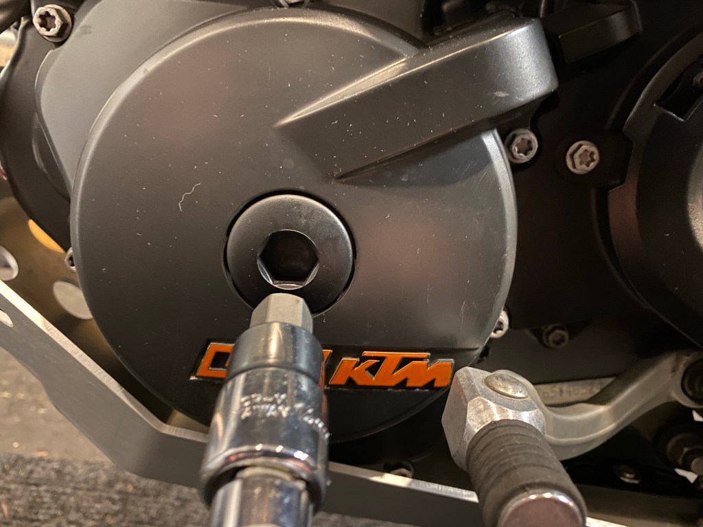
There are 2 methods of rotating the motor. One is to get the rear wheel off the ground and turn it while the bike is in gear. The other (which we prefer) is to turn the crank manually, using the crankshaft bolt which is accessed through the left side cover.
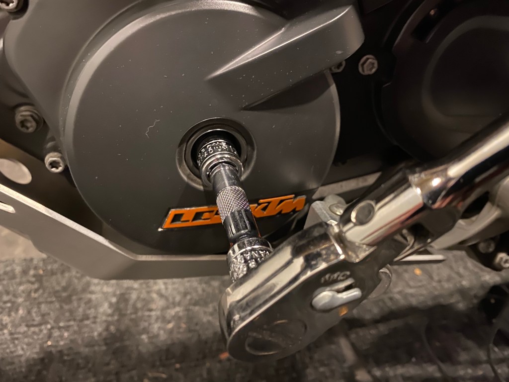
Remove the plastic cover using a hex socket to reveal the crankshaft bolt which you can rotate with a ratchet.
It will be easier to turn the motor if you remove the spark plug, but it’s not necessary. If you do decide to remove the spark plug (14mm thin-walled spark plug socket), note that the spark plug cap fits very tightly and can be difficult to remove. Be careful not to damage the connection by pulling from the wire.
Rotate the motor and keep an eye on the timing chain sprocket. If you haven’t removed the spark plug, it will require a little effort but you don’t damage anything.
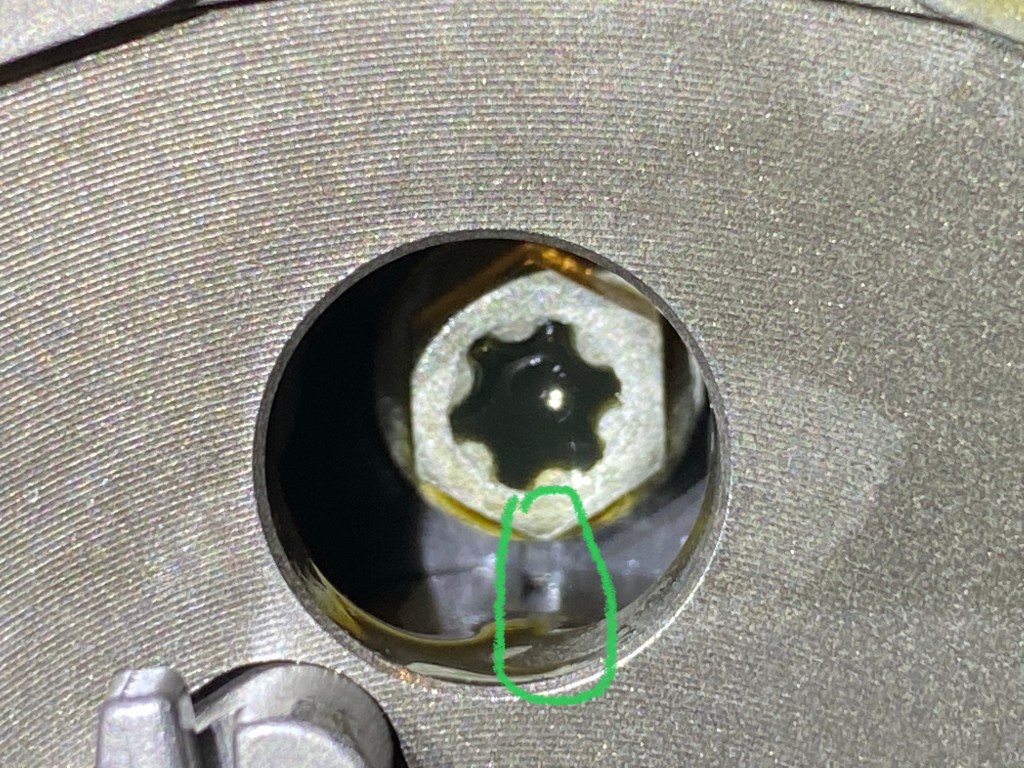
Of the 3 cam sprocket holes, you are looking to align the middle hole with the faint mark under the bolt as shown in the image below. You will also feel the motor “settle” at TDC and it will easily fall to either side when you apply force to the ratchet.
4. Measure Valve Clearance
Measuring the valve clearance is actually the easy part of this DIY (getting access to the valves is a lot more work!). Check the tolerances for your bike in the owner’s manual (in the case of the 690 SMC, it’s between 0.07 and 0.13mm). Note that tolerances must be measured cold so if you’ve just gotten back from a ride, wait at least a few hours for the bike to cool down before measuring.

To measure the clearance, take a feeler gauge that’s at either end of the tolerance range and see how it moves between the rocker arm and valve shim. If you need to force the feeler gauge, go down a size and if it slides without any resistance, go up a size until you find the feeler gauge that slides with only minimal resistance.
Note that if you are replacing the rocker arms as part of this service, you don’t need to do any pre-measuring as the tolerances will be different when you install the new rocker arms.

Write the gap value down somewhere along with the corresponding valve you measured (eg. Intake left, Intake Right, Exhaust Left, Exhaust Right). Repeat this procedure for all 4 valves. If everything is within spec, you can skip to Step #11.
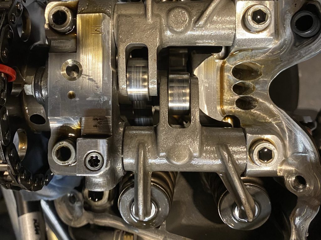
5. Remove Rocker Arms
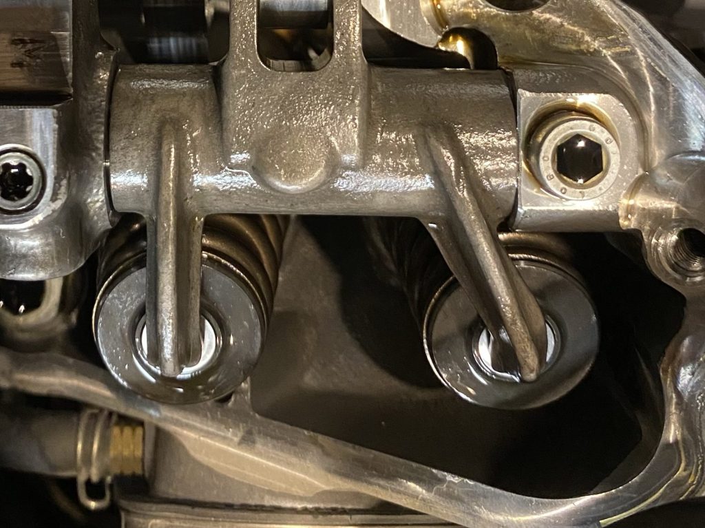
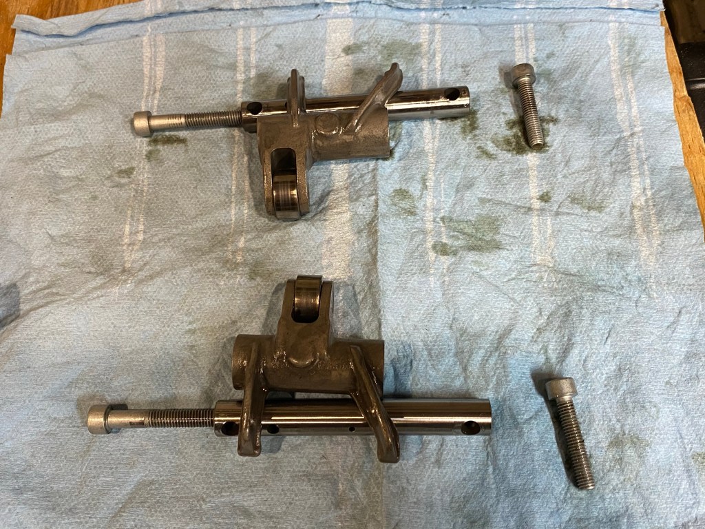
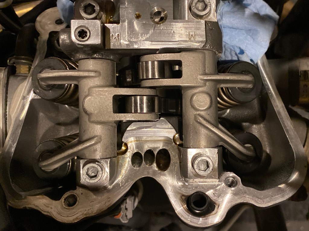
Replacing the shims requires the removal of the rocker arm of the corresponding side. For example, if your valves were only out of spec on the intake side, you can remove that side only. There are 4 hex bolts that secure the rocker arms (as shown below). Once the bolts are out, the rocker arms will be held in by metal shafts which must be extracted through the aforementioned holes in the can timing gear (left side of the bike).

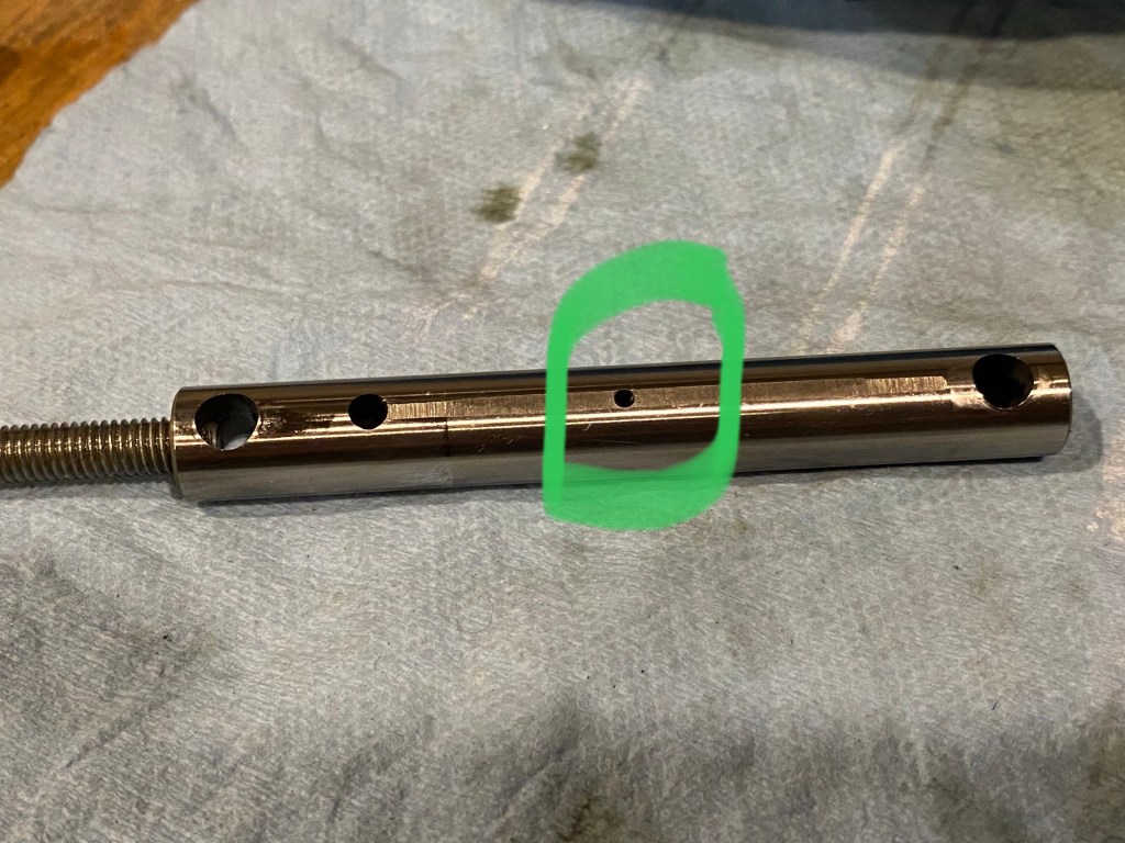
The shafts slide out (sometimes requiring a bit of force) but but are threaded on one end so that you can use the bolts from this step to pull them out. Take note of the orientation of the shafts once extracted as they are assymetrical. The flat side with the holes should be pointing up when you re-assemble them.
This is a good time to inspect the rocker arm(s) for wear and determine if replacement is required. The main failure point of the rocker arm is the bearing. Check the bearing by rotating it and pressing it to each side. It should have very minimal side-to-side play and no rotational play at all.
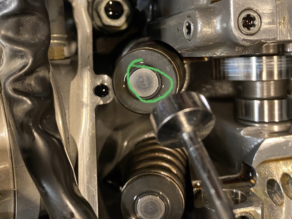
6. Remove and Measure Valve Shims
With the rocker arms out of the way, you can simply pull the required valve shims out using a magnet tool. As you take the shims out, be sure to mark them so that you know which valve each shim came from. This will be important to calculate the new shim value.
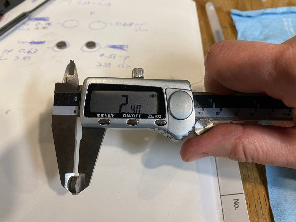
Using calipers, measure the thickness of the shim you removed and mark that value. Repeat the process for all shims.
Step 7: Calculate New Shim Values
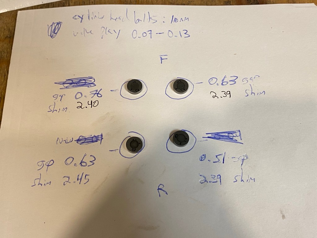
Calculate the new shim values using the formula: new shim thickness = (old gap + desired gap) – old shim thickness. See table below for an example where all 4 shims were replaced.

Step #8: Install New Shims

The first step of installing the new shim is to measure the new shim to confirm thickness. Make sure you have rags stuffed in any holes in the motor, just in case you drop the little metal shim. Carefully, press the shim into the seat. It should click firmly to confirm it’s properly seated. Repeat for all shims you are replacing.
Step #9: Install Rocker Arms
Once you have properly cleaned the rocker arms and shafts, you can cover them in either assembly lubricant or fresh motor oil. Align each rocker arm with the mounting holes and slide the rocker arm shaft through, using the threaded bolt from step 5. Remember that the shafts are directional and must be inserted with the flat side facing up. If any parts look anything less than well lubriacated, apply a little engine oil for additional protection. Torque the rocker arm bolts to 12 Nm.
Step #10: Measure New Valve Clearance
The last step of the valve adjustment is to verify the new gap of the valves you replaced. Before doing this, rotate the crankshaft once or twice and put the motor back at TDC, as described in Step 3. Finally, repeat Step 4 to make sure all valves are within spec. If any valves are out-of-spec, you made a mistake somewhere in the process. Take note of the new values and go back to Step 5. If everything is within spec, the valve adjustment is complete and you can move on to re-assembly.
Step #11: Install Valve Cover and Gasket
Before replacing the valve cover, inspect the gasket and replace it if there is any sign of wear. Use a rag and clean the mating surface on the motor to ensure the gasket seals properly.
Getting the valve cover back on takes a bit of work. Make sure all the connectors and hoses are out of the way and avoid using force as you could damage the gasket. All 4 of the bolts are the same and should be torqued to 10 Nm.

Step #12: Re-Assemble Airbox
Repeat Step 1 in reverse, paying particular attention to re-connect hoses and electrical connections. Use zip ties to secure wiring in place as necessary. If you removed the spark plug earlier, make sure to re-install (or replace) and torque to 25 Nm as per OEM specification.
Step #13: Start the Bike

The moment of truth. Start the bike. It should turn over and start easily. Hard starting could be a sign that the valve clearances are off. If the bike starts, let it warm up, inspect the head for any leaks, then take if for a test ride.

Leave a comment